can sketchup do 2d drawings to 3d models
Table of Contents
- Introduction
- An introduction to using different source material for modeling
- Trace-over modeling
- Modeling from photos
- Applying textures from a photograph
- Importing CAD files
- Earlier importing a CAD file
- Steps when importing CAD files
- Common bug when importing a CAD file into SketchUp
- Using CAD files for modeling
- Using 2D CAD linework
- Using 3D CAD files
- Model optimization of 3D CAD files
- Automating polygon reduction
- Polygon reduction software
Introduction
Now that you take a basic understanding of SketchUp, you need to decide how SketchUp fits into the framework of design in your office. By its non-procedural nature, SketchUp does non crave a certain series of steps to attain a given task. As you progress in your utilize of the software, you may observe that you use several different methods to accomplish a recurring chore, depending upon the context of the current model. This is skillful, and is as it should exist. We exercise not proscribe a item methodology or work menstruum.
An introduction to using different source fabric for modeling
There are several workflows that can exist identified as common to building product manufacturers. We take produced several videos which make information technology easier to explain them, and they are linked below. Existing CAD models provide very accurate geometry which makes over-modeling improvements in SketchUp far easier and quicker, using the CAD model for reference while placing new geometry. Over-modeling refers to either trace-over modeling or model optimization.
Trace-over modeling
 There are two types of trace-over modeling workflows based upon the CAD input used. One is from 2d CAD files, the other is when you use scanned images such equally PNG, JPG, and PDF.
When working from 2nd CAD linework, keep the CAD import as a component which you lot will utilise for reference when trace-over modeling.
Do not explode the CAD file to use the linework in SketchUp. It is all-time to create new SketchUp edges, and let the face finder in SketchUp skin the model with faces every bit you go.
 You tin can also model from an image file. This is ordinarily based upon traditional CAD output, which contains several 2D views of plan, sections, and elevations of the item.
Modeling from photos
 Y'all can as well model from a photo of a product. This is a very advanced technique and requires great intendance when setting upwards the model in the start identify. It lends itself better to angular forms, although it can be used effectively to apply photo textures to more organic forms.
Applying textures from a photo
 You can tweak a photograph and use it equally a projected texture onto a 3D model to reach adept graphic results. This enables you to add realistic visual detail to areas of the model without calculation to the polygon count.
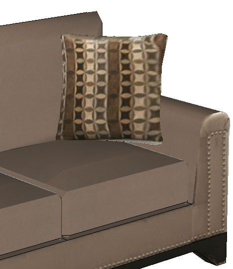
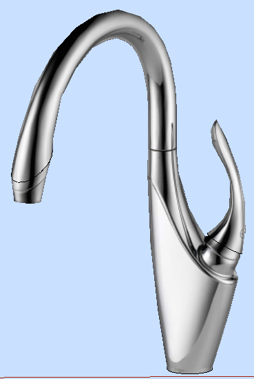
Here, the photo adds all the buttons along the arm of the chair, without having to model each button. The cushion uses 1 image beyond a smooth surface, rather than modeling each surface area of color.
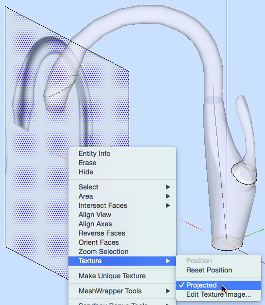 This instance shows how to add a picture of a faucet to a 3D model of the faucet. Pigment a face with the picture as a texture. Orient the painted face up to the model (using X-ray manner in SketchUp). Right click [context click] on the confront and select Texture > Projected. And then sample the paint, and paint it onto the model geometry.
Importing CAD files
Before importing a CAD file
Brand sure there is at least 1 element or line in your model prior to CAD import (even a single line will suffice). This will import the CAD file as a single component, with its linework isolated from the rest of the model. Watch this video of importing CAD files into SketchUp for the import file types DWG/DXF, STL, 3DS, and IFC.
Steps when importing CAD files
- Optional: Prep the CAD file for SketchUp import.
- Run very large 3D files (larger than 20Mb) through a poly reducer to make modeling in SketchUp more responsive. If possible specify the granularity of the triangle export.
- For 2d files, export multiple CAD files limiting layers as appropriate in each to manage ataxia when in SketchUp. Specifically turn off all text and dimensions and their leader lines and then that they do non import as linework.
- File > Import, and fix drawing units, and make up one's mind whether to preserve the drawing origin.
- Group the import geometry.
- If any geometry exists in the model, the import volition go a component automatically.
- Lock the import geometry prior to remodeling.
- Brand at least 2 Scenes to control visibility of the CAD linework:
- import on
- import off
- Delete all CAD layers moving them to Layer0 (default layer).
- Brainstorm trace over of the CAD edges.
- Develop groups and components as you describe.
- Assign groups and components to your layer scheme.
Common bug when importing a CAD file into SketchUp
Many manufacturers already have existing 2D and 3D CAD files of their products, and they wish to reuse these files directly in SketchUp. There are several issues common to CAD files that brand working with them directly in SketchUp problematic.
CAD file scale
You take to know the original scale of the CAD file (anxiety, inches, metric) so that SketchUp can be fix to compensate for this during file import. Once the file is imported into SU you can work in any units yous want, SU will exercise the conversion seamlessly.
Sometimes you may find that triangles (faces) get dropped out of a file import coming from engineering CAD 3D models. If this occurs, try setting the base units higher for the file during import. So if a setting of mm or inches is dropping out triangles, endeavour importing every bit cm or anxiety.
After the file import, scale the geometry back down to actual size. To do this, edit into the component and measure a known edge with the Tape Measure tool, and blazon the right value for the altitude measured. SketchUp will scale all elements within the electric current context proportionally.
Note: When rescaling, all sub-components in the context get re-scaled and re-positioned. This does not change the actual definition of the sub-component. The sub-component definitions retain their original size, and if you bring ane in from the component browser, it volition still be at its original size. It is best practice to right (context) click on each sub-component and select Scale definition to redefine each component'due south "native" size for future use.
CAD file origin
Many CAD files that come from civil technology programs accept their origin points set to a particular world coordinate. Hence, your incoming geometry may be set very far away from the current SketchUp origin, fifty-fifty though there is nothing betwixt the incoming geometry and the 'earth' origin. You tin ensure that the imported geometry is placed at the origin in SketchUp by making sure that the Preserve Cartoon Origin box is not checked before starting the import.
Disconnected edges in a CAD file
A CAD file can look okay and nonetheless, for whatever reason, it can accept disconnected edges that exercise not meet exactly endpoint to endpoint. In SketchUp faces are formed by a closed loop of edges that all impact endpoint to endpoint and lie in the same plane. When these CAD lines import into SketchUp, they will still non see, and hence surfaces cannot be formed from these edges, hence the import will announced to drop faces from the model.
SketchUp'south face up finder engine tin resolve edges down to 1/1,000 of an inch. Withal, for models with geometry far from the origin or with large separation of geometry within the model, sometimes faces tin can drop out during import of a file because the face finder cannot resolve them. This is due to the compounding of floating bespeak number rounding, and hence the endpoints no longer match exactly to form a closed loop.
CAD files sometimes take small edges that hang off a closed loop. These 'hanging edges' tin crusade the SU face finder to fail at creating faces even though there is a closed loop of edges nowadays. For this reason, using CAD lines can exist peculiarly problematic.
CAD file layers
CAD treats lines separately from one another based upon layering. In SketchUp, all free edges (those non encapsulated in a Group or Component) will merge one with another, regardless of their layer of origin. This can cause defoliation during import where lines on dissimilar layers cross over i another causing merging and breaking of i some other.
A method to help avoid the overlapping issue is to save out multiple CAD files, exporting groups of layers at a time, essentially 'presorting' your edges as they come up into SU.
In SU information technology is best to model everything on Layer0. Assign layers to things only after you have made groups and components of them.
Using CAD files for modeling
For all these types of over-modeling explained below, there are methodologies that can aid with your speed and efficiency. Inferring and the Paste in Place role are invaluable for a adept modeling workflow. See the article SketchUp all-time practices and applied principles for a good discussion of this method. You should also consider component hierarchy and naming within your models.
The goal is to get your products on 3D Warehouse and expose them to a world of architects and designers. To get everybody on the same page, we have developed a checklist that should assist you lot double-check that yous've created beautiful, useful, and like shooting fish in a barrel-to-operate 3D Warehouse models. To go with the checklist, we've also created an commodity and a video serial that digs deeper into what each item on the checklist means to help you accomplish the desired results.
Using 2D CAD linework
For all these reasons mentioned in the previous department, it is often desirable to use the 2D CAD linework import as an underlayment to the modeling procedure. We recommend that yous Do non use 2nd CAD line work to form faces, use CAD linework to trace over. Using the inference endpoints and midpoints of CAD lines allows y'all to be very precise while cartoon, without merging to the CAD source linework.
Tracing over top of CAD lines allows you to control the minimum size of faces y'all create. You also control the number of faces used. Y'all can also split overlapping edges and faces into separate groups or components, keeping their shapes separated. This remodeling allows you to determine layering as the model evolves. Remodeling also insures that your model faces close as you lot expect them to, hopefully avoiding whatever open loop problems.
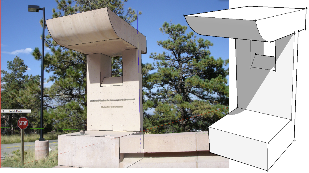
 A dandy use of inferring is when you lot want to draw from an imported 2D image file to create a 3D object. Hither, we hover the rectangle tool over the side of the cooling unit and hold Shift to lock to that plane below. Then describe a rectangle using the CAD paradigm in a higher place for the reference points. The points are traced on the CAD paradigm, and the inference lock projects them downward onto the face up. Unabridged models tin can be generated using this method. (also from 2D CAD vector files)
Using 3D CAD files
Source CAD files that are 3D already contain surfaces, and they come up into SU as faces. If you cull to use the 3D CAD geometry equally SU model geometry, you volition need to pay detail attention to the layers coming in from CAD, and the component naming and nesting coming in from CAD. Usually 3D CAD files do non suffer from hanging edges, merely they do tend to accept very dense geometry (lots of faces) and tin have missing faces due to the math rounding issues discussed to a higher place.
SketchUp has the ability to hide triangle (face) edges in a unique style, such that the face and all adjacent faces that share its edges are treated equally one continuous "polish" surface. Using smooth edges on a high poly model transforms information technology from a blackened image to a soft shaded model. Merely the heavy polygon count remains.
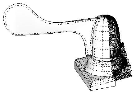
The polygon count (number of faces) affects the product component file size. In plough, this affects the operation of any SketchUp model into which it is placed. In this example, a bathroom design involving 10 faucets would add 7.3 Megabytes to the overall design file for just the faucets, whereas using a reduced poly version would only increase the design file size past 228 Kb. It does not have long for high poly count product files to make an AEC building design file sluggish, large, and unworkable.
Model optimization of 3D CAD files
 For the model optimization workflow, you supercede complex geometry with optimized geometry, thus decreasing the polygon count and hence file size. The goal here is to simplify the model geometry, while nonetheless representing the product accurately. Many CAD generated 3D models correspond surfaces very accurately with very dense geometry. A small radius can get the same triangulation as a larger bend. Good 3D Warehouse models practise not require this level of detail.
Hither is a video series showing the optimization of a faucet fixture.
Within this series, several advanced optimization methods are explored. The method yous use is based upon the nature of the object being modeled. Then to develop 1 production model ( eg a faucet) you may employ several modeling methods, 1 for the handle, another for the spout, etc. The faucet series linked above shows the post-obit methods: the Push/Pull Scale & Rotate method, Align axes & Scale method, Profile & Follow Me method, Merge Surfaces with Move Tool method, Offset chamfer method, Perimeter Contour Modeling method, and the Push/Pull & modify profile method.
Automating polygon reduction
 Poly reduction (sometimes referred to as decimation or re-sampling) is very often required when moving from engineering based 3D CAD geometry into SketchUp. There are several software programs which automate poly reduction to one degree or another. The trick is to have the simplified object nevertheless announced as shut to the original every bit possible in detail and outline. For most hard edge blazon models where members are a specific diameter or curvature, automatic decimation degrades the exact nature of the hard edge elements, causing tubes to become serrated, and hard edges to become rounded.
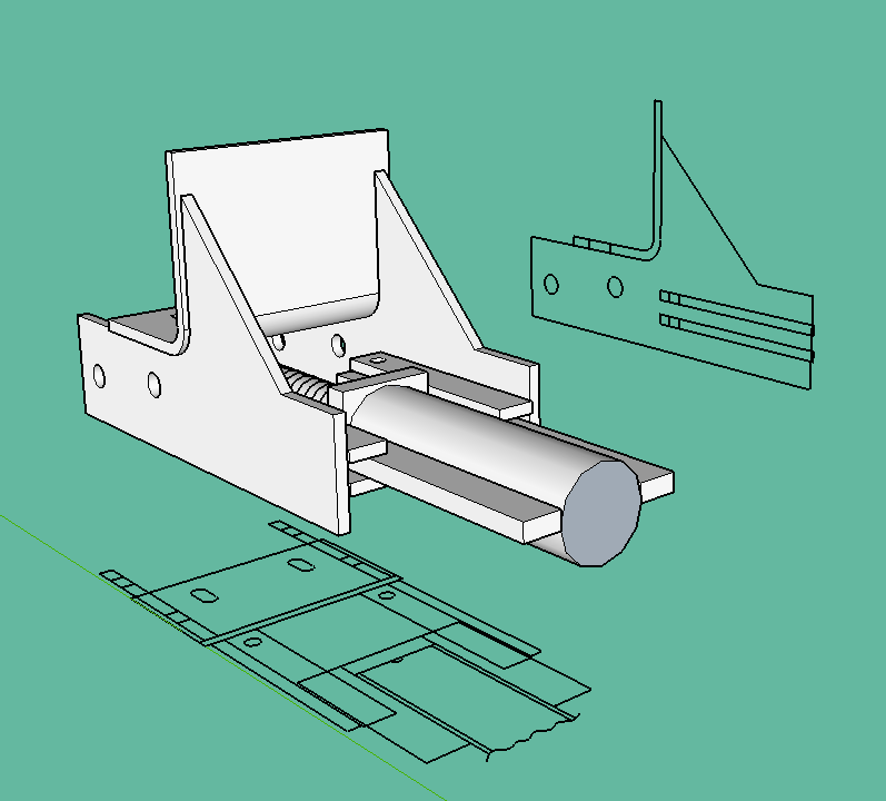
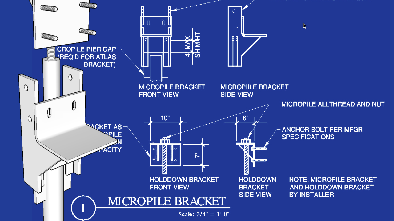
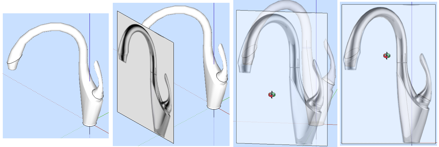
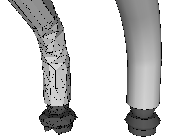
It is recommended that you model over top of 3D CAD generated geometry, rather than using the original CAD linework for a 3D Warehouse component. Optimizing a model directly with SketchUp modeling creates a very clean and tight model, minimizing poly count and maximizing approximation of the bounds of the original product, because you lot are snapping to exact points on the original polygons.
In the faucet example shown above, the new faucet geometry was modeled directly over the original CAD linework, which was File > Imported and fabricated into a group outset. The CAD linework was used as a reference when aligning new geometry and push button/ pull, move, and scale operations to each other. This allows the modeler to exist accurate to the physical dimensions and constraints of the actual product.
Come across the article: Making a detailed model in a lightweight way for best practices in SketchUp over modeling. The video Importing CAD files into SketchUp discusses the different types of CAD that tin be brought into SketchUp.
Polygon reduction software
One handy tool for reducing polygon count is the MeshWrapper, which wraps a regular mesh grid around the outside of a selection of object(due south). This is useful for simplifying organic products prior to poly decimation considering it distributes an fifty-fifty set of points beyond the selection. Another handy surfacing tool driven by paths and profiles is Curviloft or here and here.
Technology CAD files can be simplified prior to import into SketchUp using polygon decimation software such as PolyTrans from Okino Computer Graphics and Simplygon Cloud https://www.simplygon.com/ , and MeshLabs from SourceForge which is an open up source project. An efficient workflow is to use a combination of automated poly reduction and SketchUp modeling.
Source: https://help.sketchup.com/en/how-model-efficiently-using-existing-2d-and-3d-sources
0 Response to "can sketchup do 2d drawings to 3d models"
Enviar um comentário